Flexible PCB Manufacturing: What Engineers and Product Teams Need to Know
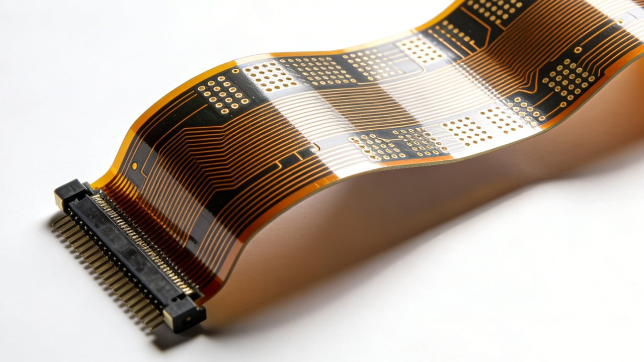
Flat, foldable, and able to survive thousands of flex cycles without cracking—flexible printed circuit boards have quietly become one of the most important building blocks in modern electronics. From the hinge in a foldable phone to the ribbon connector inside a medical wearable, flexible PCB manufactur solves a problem rigid boards simply can’t: fitting complex circuitry into tight, curved, or moving spaces.
If you’re designing a product that needs to be thin, lightweight, or capable of bending without breaking, understanding how flexible PCBs are made isn’t just useful background knowledge—it directly shapes how you design the board, choose a manufacturing partner, and avoid costly redesigns later.
This article breaks down what flexible PCB manufacturing actually involves, the materials and processes behind it, common design pitfalls, and what separates a reliable flex PCB supplier from one that will cause you headaches down the line.
What Is a Flexible PCB, Exactly?
A flexible printed circuit board is a circuit built on a bendable substrate—typically polyimide—instead of the rigid fiberglass (FR4) used in standard PCBs. The copper traces are laminated onto this thin, flexible film, allowing the board to bend, fold, or twist repeatedly without the conductors fracturing.
Flex PCBs generally fall into a few categories:
- Single-sided flex – One conductive layer, used for simple interconnects.
- Double-sided flex – Two conductive layers with plated through-holes.
- Multilayer flex – Three or more layers, used when routing density is high.
- Rigid-flex – Combines rigid PCB sections with flexible connecting sections in a single board, eliminating the need for separate connectors between boards.
Rigid-flex deserves special mention because it’s increasingly common in devices where space and reliability both matter—think aerospace avionics or compact medical devices—since it removes connector failure points entirely.
Why Manufacturers and Designers Choose Flex PCBs
The appeal isn’t just about bending. Flex circuits solve several engineering problems at once:
Space and weight reduction. A flex circuit can replace bulky wire harnesses and connectors, which matters enormously in aerospace, wearables, and automotive applications where every gram counts.
Improved reliability in dynamic applications. Where a wire harness might fatigue and fail after repeated movement, a properly designed flex circuit is engineered to withstand thousands or even millions of flex cycles, depending on the bend radius and copper type used.
Better signal integrity in dense designs. Because flex circuits allow tighter, more controlled routing, they can reduce electromagnetic interference compared to loose wiring.
Design freedom. Flex PCBs can be folded into three-dimensional shapes, allowing electronics to conform to unusual product enclosures rather than forcing the enclosure to accommodate a flat rigid board.
The tradeoff is cost and complexity. Flex manufacturing involves more specialized materials and tighter process control than standard rigid PCB fabrication, which is why flex boards typically carry a higher per-unit cost.
The Core Materials Behind Flexible PCB Manufacturing
Material selection has a bigger impact on flex PCB performance than most first-time designers expect.
Substrate: polyimide vs. PET. Polyimide (often sold under the trade name Kapton) is the dominant substrate for flex PCBs because it tolerates high temperatures, resists chemicals, and holds up well through repeated flexing. PET-based substrates are cheaper but can’t handle soldering temperatures, so they’re generally limited to simple static applications like membrane switches rather than true dynamic flex circuits.
Copper type: rolled annealed vs. electrodeposited. This choice matters more than many designers realize:
- Rolled annealed (RA) copper has a grain structure that runs parallel to the foil surface, giving it much better fatigue resistance under repeated bending. It’s the standard choice for dynamic flex applications.
- Electrodeposited (ED) copper is cheaper and fine for static or single-bend applications, but it cracks sooner under repeated flexing because of its vertical grain structure.
Specifying ED copper on a board that will flex thousands of times during its product life is a common and expensive mistake.
Adhesive vs. adhesiveless construction. Traditional flex laminates use an adhesive layer to bond copper to the polyimide film. Adhesiveless constructions bond copper directly to the substrate, resulting in a thinner board with better flexibility and higher thermal reliability. Adhesiveless flex costs more but is generally preferred for high-reliability or high-density applications.
How Flexible PCBs Are Manufactured: Step by Step
While every fabricator has its own process nuances, flexible PCB manufacturing generally follows these stages:
- Material preparation – The polyimide substrate is cleaned and inspected before copper lamination.
- Copper lamination – Copper foil is bonded to the substrate, either with adhesive or through direct deposition.
- Circuit imaging – A photoresist layer is applied, and UV light exposes the circuit pattern based on the Gerber files provided.
- Etching – Chemical etching removes unwanted copper, leaving only the designed traces behind.
- Drilling and plating – For multilayer or double-sided boards, holes are drilled and plated to create electrical connections between layers.
- Coverlay application – A polyimide coverlay (rather than standard solder mask) is laminated over the circuit to protect traces while preserving flexibility.
- Stiffener attachment – Rigid stiffeners are bonded to specific areas, usually where connectors will be mounted, to provide mechanical support without sacrificing flexibility elsewhere.
- Electrical testing – Every board is tested for continuity and shorts before shipment.
- Final cutting/routing – Boards are cut to their final outline, often using a die or laser cutting process for precision on complex shapes.
The coverlay step is worth pausing on. Unlike rigid PCBs, which use liquid solder mask, flex boards need a flexible protective layer that won’t crack when the board bends. Getting this wrong—using the wrong coverlay thickness or adhesive—is one of the more common causes of premature trace failure.
Common Design Mistakes That Cause Manufacturing Problems
Even experienced hardware engineers run into flex-specific issues that don’t apply to rigid board design.
Ignoring bend radius guidelines. A tight bend radius concentrates mechanical stress on the copper traces. Most fabricators recommend a minimum bend radius of at least 10 times the board thickness for static applications, and considerably more for dynamic flexing. Violating this dramatically shortens the board’s usable life.
Routing traces perpendicular to the bend axis instead of parallel. Traces that run parallel to the fold line experience far less stress than those crossing it at an angle, which matters a lot in the bend area.
Placing vias or component pads in the flex zone. Any solid feature—a via, a pad, a stiffener edge—creates a stress concentration point. These should sit in static regions of the board, not in areas meant to flex.
Underestimating trace width requirements for current-carrying capacity. Because flex circuits often use thinner copper than rigid boards, the same current draw can cause more heating. Current-carrying calculations need to account for the specific copper weight being used.
Skipping a DFM review with the fabricator. Flex manufacturing tolerances differ from rigid board tolerances, and a design that looks fine on paper may not be manufacturable at the intended cost or yield.
Choosing a Flexible PCB Manufacturing Partner
Not all PCB fabricators handle flex work well, since it requires different tooling, materials handling, and quality control than standard rigid board production. When evaluating a manufacturer, it helps to ask:
- Do they manufacture flex and rigid-flex in-house, or outsource part of the process?
- What copper types and substrate options do they stock, and can they support adhesiveless construction if needed?
- Can they provide flex-specific design rules and run a DFM check before production?
- What flex-cycle testing or reliability data can they share for boards similar to your application?
- Do they have experience with your specific bend requirements—static, dynamic, or repeated folding?
A manufacturer that primarily builds rigid boards and treats flex as a side offering will often lack the process control needed for high-reliability applications, even if their quoted price looks attractive.
Final Thoughts
Flexible PCB manufactur isn’t simply “PCB manufacturing on a bendable material.” It involves distinct material choices, layout rules, and process steps that directly affect how long the board survives in real-world use. Getting copper type, bend radius, coverlay design, and stiffener placement right at the design stage will save far more time and money than trying to fix reliability issues after production has started.
For engineers moving from rigid to flex designs for the first time, the safest approach is to involve your fabricator early, before the layout is finalized. Flex-specific design rules vary between manufacturers, and a short DFM conversation up front can prevent an expensive round of respins later.